1. Cable connection
There are two basic cable connections between the fuel sensor and MDVR.
One is to connect signal cable which is consist of yellow, blue and black 3 cables, the other is to connect power supply cable which is consist of red and black 2 cables, as shown in following Figure 1.
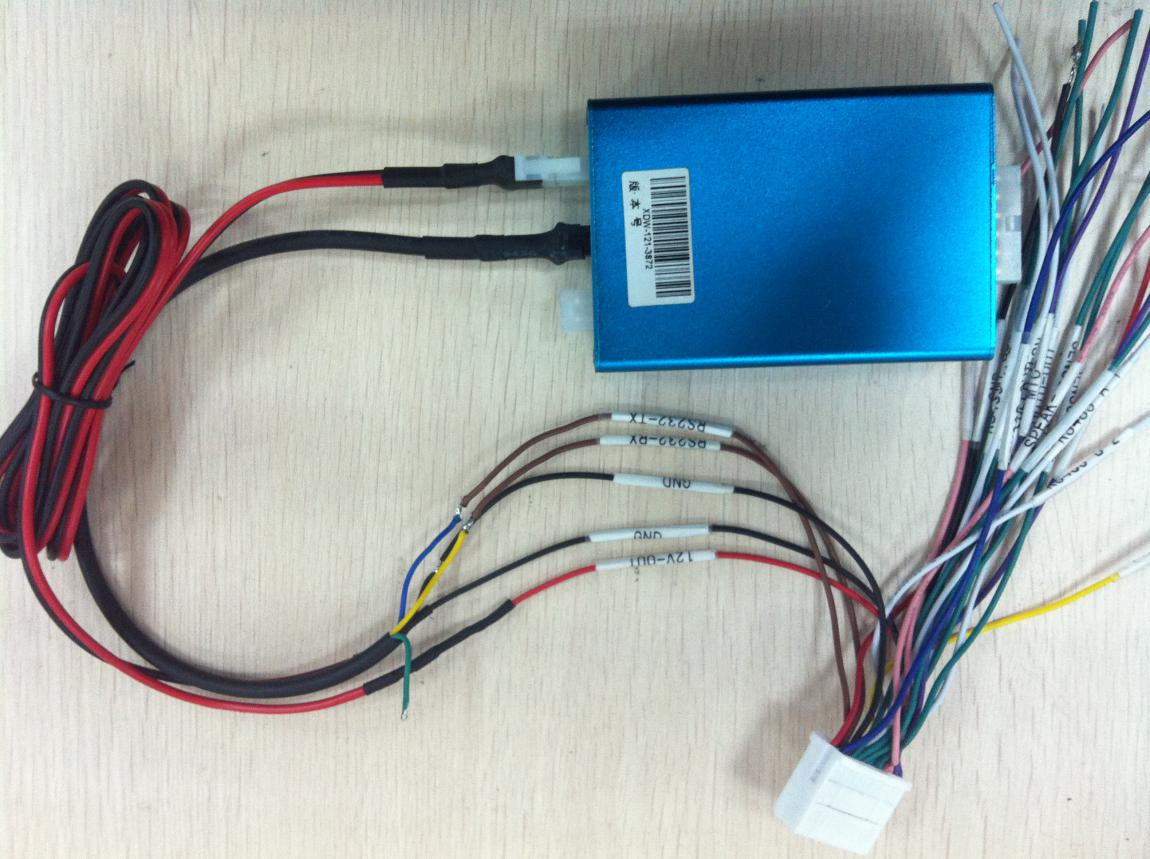
Figure 1
1.1 Signal cable connection:
-Yellow cable of fuel sensor should be connected with RS232-RX cable of MDVR
-Blue cable of fuel sensor should be connected with RS232-TX cable of MDVR
-Black cable of fuel sensor should be connected with GND cable of MDVR
1.2 Power supply cable connection:
- Red cable of fuel sensor should be connected with 12V-OUT cable of MDVR
- Black cable of fuel sensor should be connected with GND cable of MDVR
2. CMS client software setting
2.1 to log in CMS, click “others”, then click “Report Query”, as Figure 2
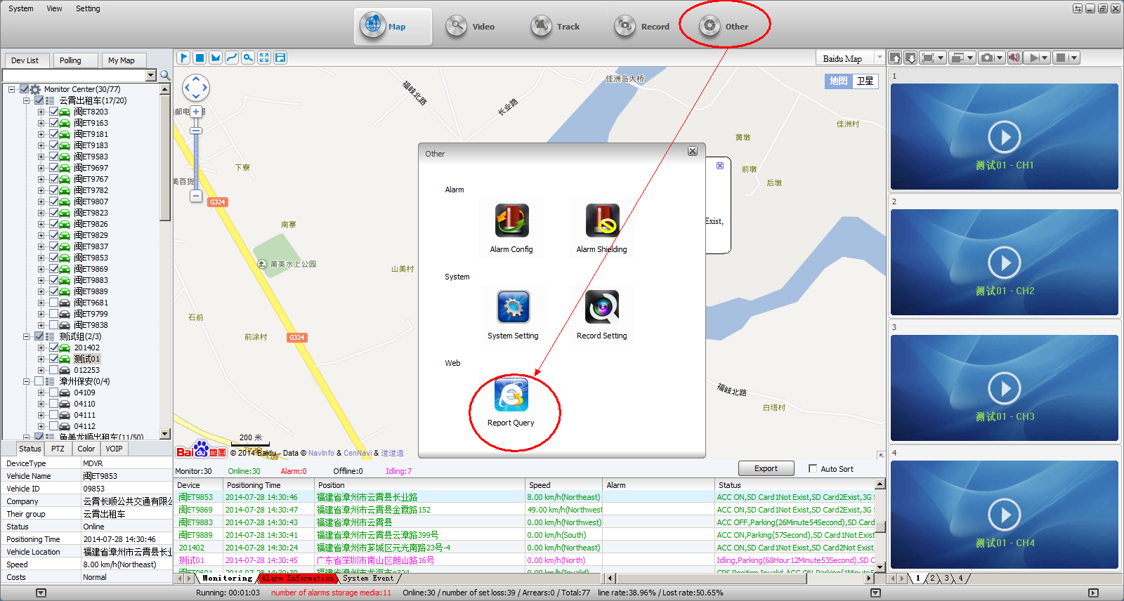
Figure 2
2.2 Vehicle Management System page will pop-out after clicking “Report Query”, as shown in following Figure 3, to click “Device”, to click the vehicle which is installed with fuel sensor, which will lead to pop-out an option window, to click “Module”, to check in the fuel sensor option, to save as completed.
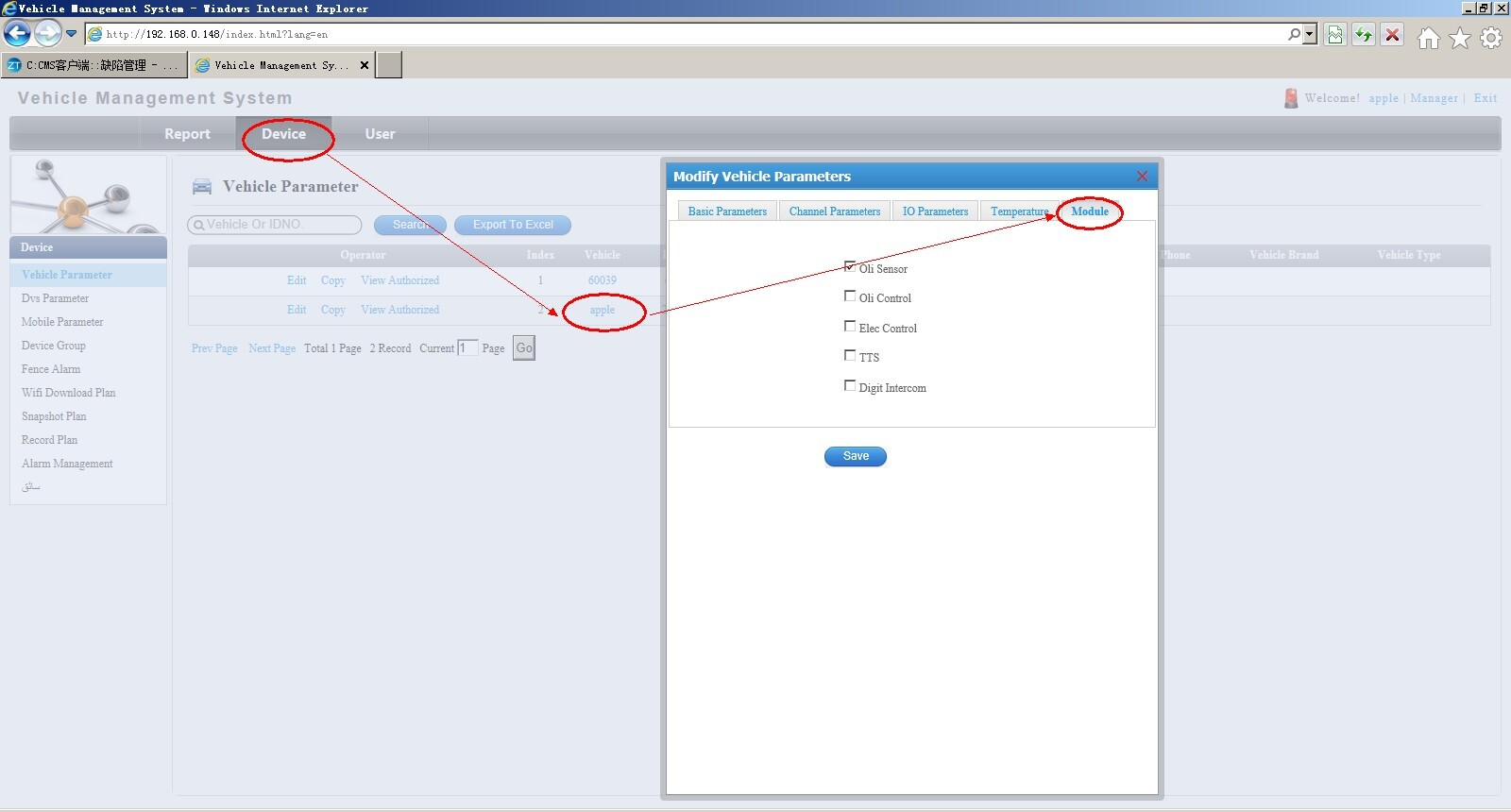
Figure 3
3. Device Setting of MDVR
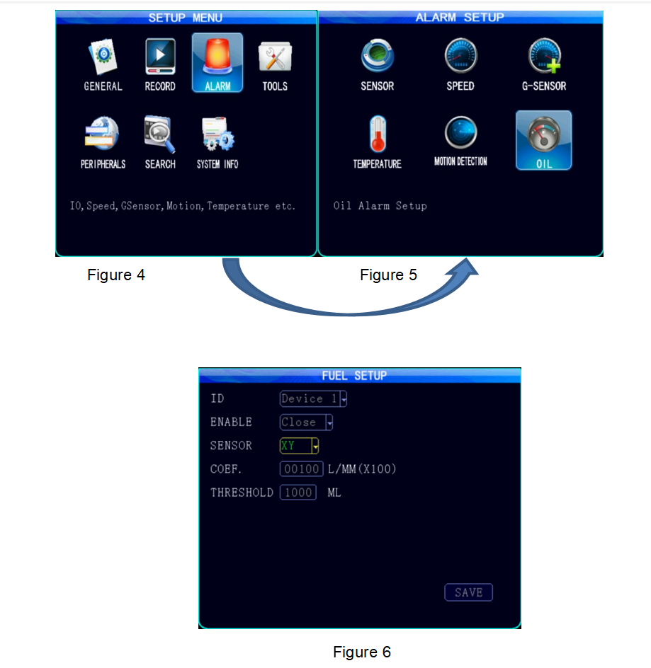
To log in SETUP MENU page, to choose “ALARM”, enter ALARM SETUP page, to choose “OIL”, enter OIL SETUP page, to set up limits in each option, as shown in Figure 4, Figure 5 and Figure 6:
If fuel volume changes hits any limits, it will trigger alarm which will be shown as alarm info on CMS client software, as well as real time fuel volume info. As shown in Figure 7:
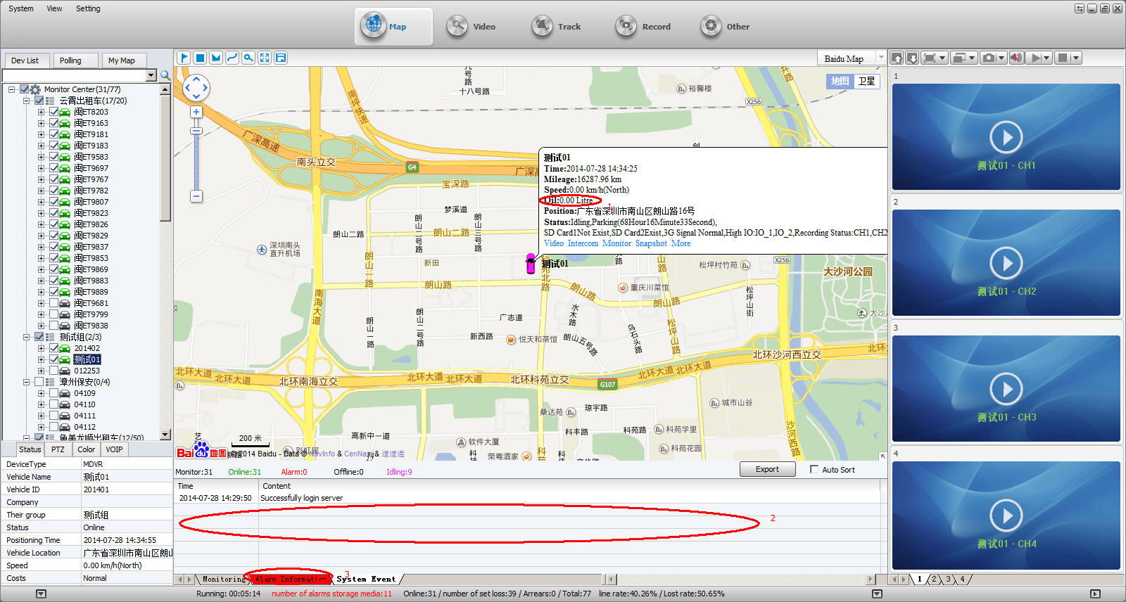
Figure 7
Download link:
![]() Connection of Ultrasonic Fuel Sensor and Mobile DVR.pdf
Connection of Ultrasonic Fuel Sensor and Mobile DVR.pdf

 Icarvisions.com
 Español
 português
 简体中文
简体中文 繁體中文
繁體中文 Deutsch
 Français
 日本語
日本語 한국어
한국어 بالعربية
 TÜRKÇE
 русский
 English
Contact Us
Questions or comments? Please fill out the form below, send a quick message, or call us. We love to hear from you!