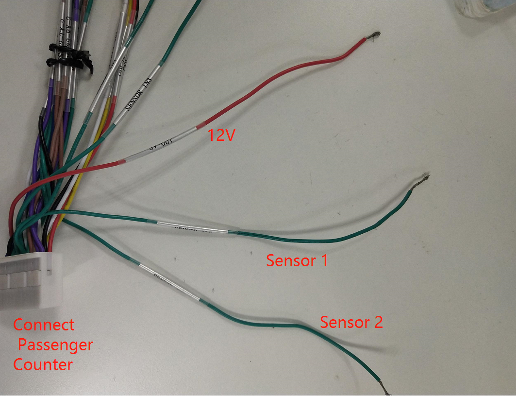
Sensor Cable connection about Passenger Counter:
(Attention!
This 24 Pin cable is connected to Passenger.)
Sensor in1 access to the front door, counter access to the front door of the switch signal;
Sensor in2 pick the back door, the counter to get the back door of the switch signal.

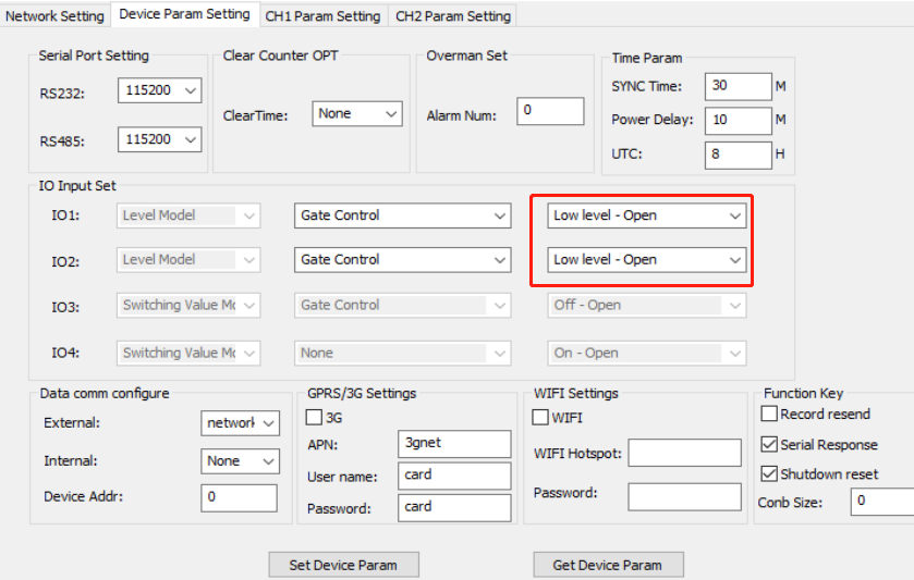
If you set Low level- Open, only when the Sensor 1 and Sensor 2 were both triggered 12V can transfer the Passenger Data to MDVR via RS -232.
Otherwise, the passenger counter will count the number when the door was open.

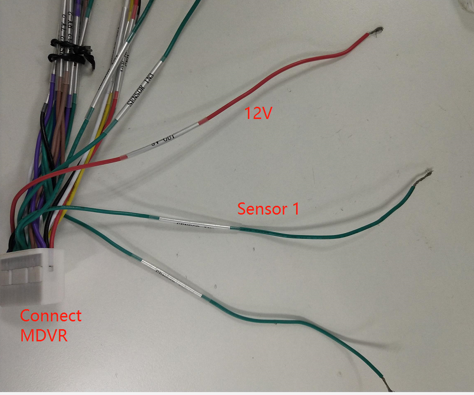
Sensor Cable connection about Panic button.
(Attention!
This 24 Pin cable is connected to MDVR.)
There will be a panic alarm when the Sensor is triggered by 12V. So you could install the panic button between the Sensor 1 and 12V.

FAQ DOWNLOAD:
![]() Differentiate IO ports to implement Passenger Counter and Emergency Button functions.doc
Differentiate IO ports to implement Passenger Counter and Emergency Button functions.doc

 Icarvisions.com
 Español
 português
 简体中文
简体中文 繁體中文
繁體中文 Deutsch
 Français
 日本語
日本語 한국어
한국어 بالعربية
 TÜRKÇE
 русский
 English
Contact Us
Questions or comments? Please fill out the form below, send a quick message, or call us. We love to hear from you!